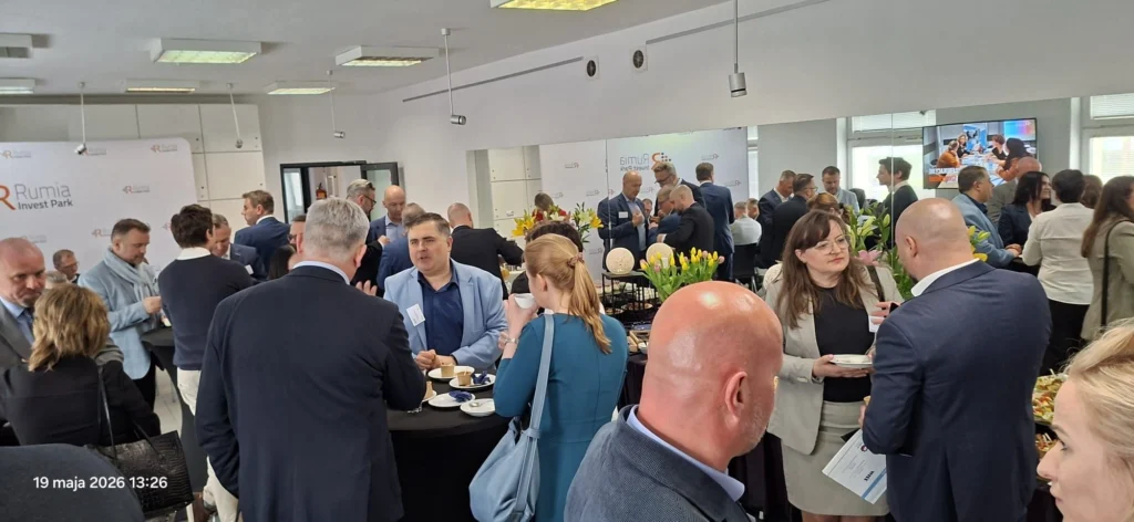
SIM Gdynia at the AHK Poland Summer Evening 2026
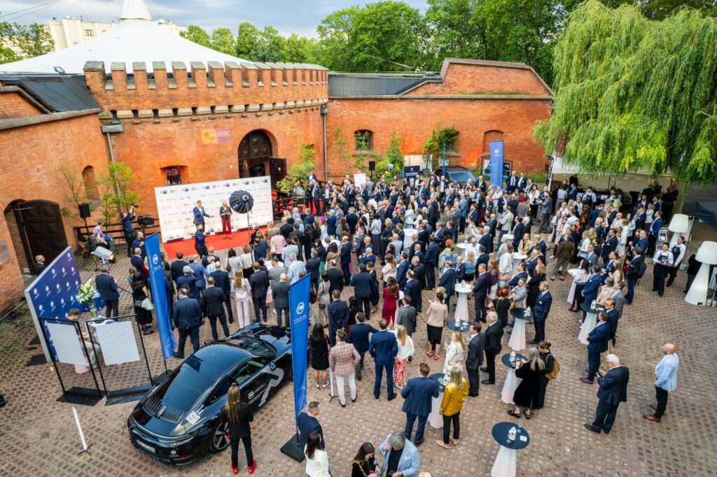
We took part in the AHK Poland Summer Evening 2026, one of the largest Polish-German business gatherings organised by the German-Polish Chamber of Industry and Commerce (AHK Poland). The event brought together more than 400 representatives of member companies, business partners and the wider business community. Held at Forteca Kręgliccy in Warsaw, the meeting provided an opportunity for discussions, exchanging experiences and building relationships between companies operating in the Polish and German markets. Discussions and new opportunities for cooperation The programme included networking sessions, business meetings and numerous discussions on the development of economic cooperation between companies representing different industrial sectors. For SIM Gdynia, participating in events of this kind is an opportunity to meet new business partners, exchange experiences and follow market developments. Face-to-face meetings help us better understand the needs of companies and build relationships that may lead to joint projects and new opportunities for cooperation in the future. The importance of business relationships Modern industry relies not only on technology and manufacturing capabilities but also on strong business relationships. This is why we regularly participate in industry events, conferences and meetings that bring together members of the business community. We would like to thank the organisers for preparing the event and all participants for the valuable discussions and exchange of experiences.
Surface Roughness Under the Microscope – From Ra to Rz: How Cutting Parameters Define Final Quality in CNC Machining
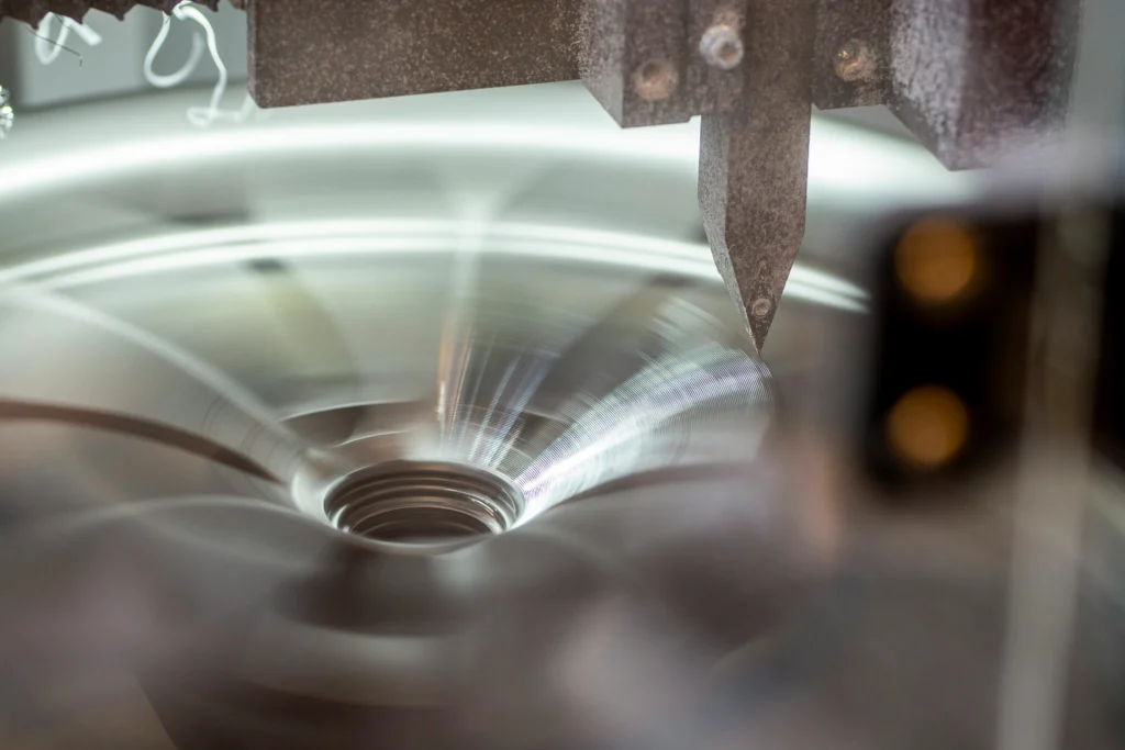
In CNC machining, dimensional accuracy is only one of the factors that determine part quality. Even a component manufactured according to the technical drawing may fail to perform its intended function if the machined surface does not meet the project requirements. For this reason, technical documentation often specifies surface roughness requirements using parameters such as Ra and Rz. Surface roughness affects not only the appearance of a component but also its durability, sealing performance, and interaction with other parts. Why Surface Roughness Matters in CNC Machining Every machined surface contains microscopic irregularities created by the cutting action of the tool. Their size and characteristics depend on many factors related to the manufacturing process. Surface quality requirements should always be adapted to the function of the component. Not every surface requires the same level of finish, but in the case of mating surfaces, guide surfaces, and sealing surfaces, roughness can directly affect the performance of the finished product. Excessive surface roughness can accelerate component wear, increase friction, or make it difficult to achieve the required sealing performance. On the other hand, unnecessarily strict surface quality requirements often lead to higher production costs. Surface quality is particularly important wherever even minor deviations can affect component functionality. A good example is the medical industry, which we discuss in more detail in the article: “CNC Machining in the Medical Industry – Surface Quality Requirements” Ra and Rz – What Do They Tell Us About a CNC-Machined Surface? Ra and Rz are among the most commonly specified surface roughness parameters in technical drawings. Both describe surface condition, but each provides information about a different aspect of surface quality. In CNC machining, roughness parameters affect component interaction, sealing performance, and durability during operation. Understanding the differences between Ra and Rz is therefore important when defining quality requirements. Why the Ra Parameter Does Not Show the Whole Picture Ra represents the arithmetic average of surface profile deviations over the measured length. It is the most commonly used roughness parameter and appears in a large proportion of technical documentation. However, Ra provides only an average value. Two surfaces may have the same Ra value while differing significantly in the shape and depth of their irregularities. From the perspective of sealing performance, friction, or component interaction, these differences may be important. For this reason, when planning a CNC machining process, evaluating surface quality based on a single parameter does not always provide enough information to determine the actual requirements of the component. When Rz Becomes More Important Rz describes the height of surface irregularities, taking into account the differences between the highest peaks and deepest valleys of the profile. This makes it possible to evaluate not only the average surface condition but also larger irregularities that may affect component performance. This parameter is particularly useful when evaluating mating and sealing surfaces, as well as components exposed to operational wear. It can help identify local irregularities that may affect sealing performance or component durability. For this reason, in many industrial applications, Rz analysis provides valuable additional information alongside Ra measurements. What Determines Surface Roughness After CNC Machining? Achieving the required surface quality in CNC machining is not the result of a single technological decision. Even when working from identical technical documentation, the final result may vary depending on machining parameters, material properties, and tool condition. Surface roughness requirements should therefore be considered in the context of the entire production process rather than a single machining operation. Cutting Parameters and Tool Condition Machining parameters are among the most important factors affecting surface quality. Feed rate, cutting speed, and depth of cut directly influence the characteristics of the marks left by the cutting tool. In our work, we often encounter situations where a seemingly minor adjustment to machining parameters has a greater impact on the final surface quality than the choice of material itself. Tool condition is equally important. A worn cutting edge can reduce surface quality, increase surface irregularities, and produce unwanted machining marks. Workpiece Material and Process Rigidity Not every material behaves in the same way during machining. Aluminium, structural steel, stainless steel, and brass have different properties that affect the cutting process. For this reason, machining parameters should not be selected solely on the basis of component geometry. Material properties and the required surface quality after CNC machining are equally important. Parameters that work well for one material may not produce the same result when machining another component. The rigidity of the entire machining system also plays an important role. Vibrations generated during machining can leave marks on the surface that become visible during quality inspection. Where Are Surface Roughness Requirements Particularly Important? Not every surface of a component requires the same level of finish. Surface roughness requirements should therefore result from the function that a given feature performs in the finished product. We often work with components where surface quality requirements are just as important as the dimensional tolerances specified for CNC machining. Particular attention is paid to: Hydraulic components are a good example, as surface quality directly affects sealing performance and system durability. Surface Roughness Inspection After CNC Machining Achieving the required surface quality depends not only on the manufacturing process but also on effective inspection. Surface roughness is measured using specialised measuring instruments that make it possible to determine the required parameter values. This allows compliance with technical documentation to be confirmed before the component moves to subsequent production stages. We discuss our approach to quality control in more detail in the article: “Quality control in CNC machining – how do we ensure precision at SIM Gdynia?” Does Lower Surface Roughness Always Mean a Better Part? One of the most common mistakes is assuming that the lowest possible Ra value will always be the best solution. In our work, we often encounter situations where surface roughness requirements are stricter than the actual function of the component requires. Overly restrictive surface roughness requirements can lead to: For this reason, surface quality requirements should be defined according
Family Picnic for Children’s Day – Time Together for the SIM Gdynia Team in Chwaszczyno

On 14 June 2026, the Family Picnic for Children’s Day took place at Toyota Arena Stadium in Chwaszczyno. The event was organized with the idea of spending time together in a family-friendly atmosphere. The programme included many attractions for children and adults, such as animations, competitions, artistic performances, inflatable attractions, family sports activities and a food zone. It is an event that has attracted the local community for years and creates a space for shared celebration, conversations and good fun. We are pleased that this year we once again managed to gather enough participants to prepare a SIM Gdynia zone for our employees and their loved ones. It was a space for spending time together, talking and relaxing with prepared snacks and drinks. Time Together Outside Everyday Work Our zone was a place where we could meet outside the everyday work environment, spend time with our families and simply be together in a less formal atmosphere. It was also an opportunity to share a meal, talk and take a moment to rest during the event. Such initiatives are of great value to us because they help build relationships not only within the team, but also among families and loved ones, who are an important part of our employees’ lives. In the daily pace of work, there is not always space for such meetings, which is why we appreciate even more the opportunity to take part in local events together. Engagement in Local Initiatives For us, it is not only an opportunity for integration, but also a way to support initiatives taking place in our closest surroundings. We are happy to get involved in events that bring people together and create a positive atmosphere around spending time together. The weather was good, and the whole event took place in a friendly and family-oriented atmosphere. It was a good opportunity to spend time together and meet outside everyday professional duties. Thank you to all participants for the time spent together, and see you at the next events!
SIM Gdynia at the Polish-Swedish Defence Industry Forum

We took part in the Polish-Swedish Defence Industry Forum organised by the Ministry of Economic Development and Technology. The event brought together companies and institutions connected with the defence sector, creating an opportunity to discuss international cooperation, technological development and new investment opportunities. The forum took place at a time when cooperation between Poland and Sweden in the defence industry is becoming increasingly important. The topics discussed included opportunities to develop industrial partnerships, technology transfer, the participation of companies in international supply chains and joint research and development projects. Discussions on the future of the defence sector The event brought together representatives of public administration, technology companies and businesses operating in the defence sector. The forum provided an opportunity to exchange experiences and explore the prospects for cooperation between Polish and Swedish organisations. Particular attention was given to security, modern technologies and strengthening Europe’s industrial capabilities. Discussions also focused on the role of manufacturing companies in projects of strategic importance to the economy and defence sector. Cooperation opportunities for Polish companies The meeting brought together dozens of companies from Poland and Sweden. Each company had the opportunity to present its activities, capabilities and potential areas of cooperation. For SIM Gdynia, participating in events of this kind is an opportunity to follow market developments and build relationships with partners operating in sectors that require high quality and precision in the manufacturing of mechanical components. The growth of the defence industry and new technology projects create opportunities for cooperation between manufacturers, technology providers and production companies. SIM Gdynia in the defence sector For several years, we have been consistently developing our capabilities in the production of components for the defence sector. Participating in industry events allows us to better understand market needs, explore new directions in technological development and establish valuable business relationships. We would like to thank the organisers for the opportunity to participate in the event and everyone involved for the inspiring discussions about the future of the defence industry and international cooperation.
CNC Machining of Threaded Parts – How to Avoid the Most Common Threading and Thread Inspection Errors?
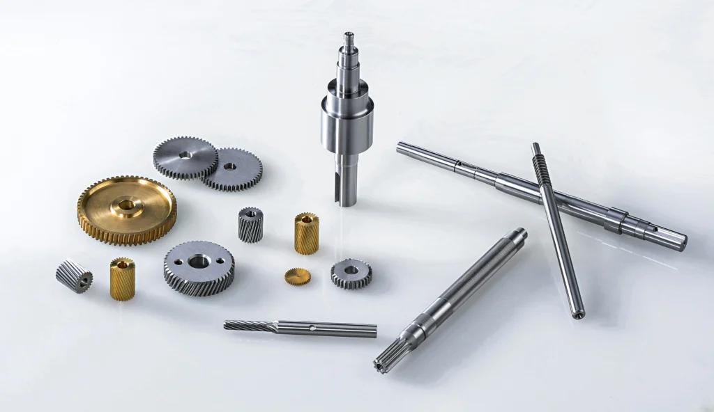
Threads are among the most commonly manufactured features in mechanical component production. They are used in simple assembly parts as well as housings, enclosures, and components operating in demanding industrial environments. Although threading may seem like a standard machining operation, even minor errors can cause problems during assembly. As a result, a part that meets dimensional requirements may still fail to perform correctly in its intended application. For this reason, CNC machining of threaded parts requires not only a properly designed manufacturing process but also effective quality control. Why Thread Quality Matters in CNC Machining Threads are responsible for ensuring a reliable connection between components. If a thread is manufactured incorrectly, the problem often becomes apparent only during assembly or the initial operation of the equipment. In many cases, minor damage to the thread profile, poor surface quality, or geometric deviations are enough to prevent a screw from being installed correctly. Thread quality is particularly important for components exposed to operational loads, applications requiring leak-tight connections, and parts designed for repeated assembly and disassembly. Where Thread Defects Most Commonly Become Apparent Not every thread-related problem is visible immediately after CNC machining. Based on our experience, many defects only become apparent during the assembly of finished components, when the connection fails to meet the specified requirements. The most common issues include: For a single part, such a problem usually means additional assembly work or the need for rework. In larger production batches, the same defect may affect multiple components, leading to additional inspections, delays, and higher project costs. For this reason, thread quality should be treated as one of the factors affecting the functionality of the finished product rather than simply another manufacturing operation. The Most Common Problems When Producing Threads in CNC Machining The final result of CNC threading depends on many factors related to both workpiece preparation and the machining process itself. In our work, we often encounter situations where thread problems are caused not by one major error but by several seemingly minor deviations occurring at different stages of production. Hole Preparation and Tool Condition One of the most common errors is improper preparation of the hole before threading. Even minor deviations in diameter, alignment, or surface quality can affect the machining process and the quality of the finished connection. Errors introduced at this stage are difficult to correct during subsequent operations, which is why proper workpiece preparation is essential for producing a correct thread. Tool condition is equally important. As tools wear, thread quality deteriorates and the risk of defects increases. This is particularly relevant in serial production, where tools perform a large number of machining cycles. For this reason, monitoring tool condition is one of the key elements in maintaining stable production quality. Thread Damage and Chip Evacuation Problems Another common source of problems is chips remaining in the machining zone. They can damage the thread surface or reduce the quality of subsequent thread turns. This issue is particularly common when producing deeper threads and machining materials that generate long, difficult-to-evacuate chips. The first thread turns are especially vulnerable because they are responsible for ensuring proper engagement during assembly. Even minor damage in this area can cause problems when joining components. Effective chip evacuation from the machining zone is therefore particularly important when producing deeper threads and in serial production. Similar relationships can also be observed in other precision machining operations. We discuss them in more detail in the article: “Precise hole machining in CNC machining – drilling, reaming, and boring in practice” Thread Inspection and Consistent Quality in CNC Serial Production Thread inspection should not be limited to visual examination. Depending on the requirements, thread gauges and other inspection methods are used to verify whether the thread has been manufactured correctly. In serial production, maintaining consistent parameters across the entire batch is just as important as the quality of an individual thread. Based on our 45 years of experience, the greatest challenge is not producing a single correct part but maintaining the same quality across subsequent production batches. Achieving this requires proper process preparation, tool condition monitoring, and regular inspection of manufactured components. Selecting appropriate tolerances and quality requirements at the technical documentation stage is equally important. We discuss our approach to quality control in more detail in the article: “Quality control in CNC machining – how do we ensure precision at SIM Gdynia?” Summary Threads are among the features whose quality is often fully verified only during assembly. Proper process preparation, tool condition monitoring, and effective inspection of finished parts therefore have a direct impact on component functionality. In CNC machining, dimensional compliance is not the only requirement. A finished part must also function correctly during subsequent production stages and throughout its intended service life. At SIM Gdynia, we provide CNC machining of threaded parts for demanding industrial applications. Contact us to discuss your project requirements.
Technological Training with ISCAR at SIM Gdynia
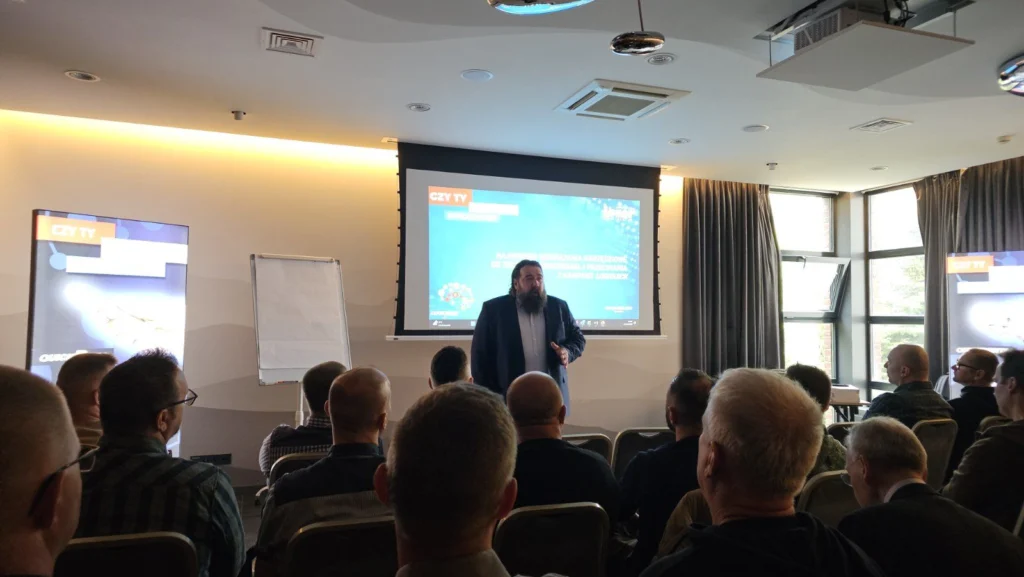
On 15 May, a technological training session conducted by ISCAR took place at SIM Gdynia. ISCAR is our partner with extensive experience in the field of cutting tools and CNC machining technology. The meeting was an opportunity for our team to expand its knowledge and learn about solutions that may support the further development of production processes carried out at SIM Gdynia. In the CNC machining industry, the development of tool technologies has a direct impact on process stability, production efficiency and the quality of manufactured parts. That is why meetings of this kind have real practical value for us. New Solutions in Cutting Technology During the training, ISCAR representatives presented the new LOGIQUICK tool line, developed for modern cutting and milling processes. Solutions from this series make it possible to better match tools to specific technological applications, which may translate into both greater precision of the processes performed and optimization of machining times. In practice, such solutions are important not only from the perspective of efficiency, but also for the repeatability of production processes, which is crucial in everyday work for the quality of finished components. Exchange of Experience and Competence Development For our team, this was not only a product meeting, but above all an opportunity to exchange experience and discuss practical aspects of cutting technology. Direct contact with technology partners makes it easier to assess the potential of new solutions and look at the production process from the perspective of everyday technological challenges. At SIM Gdynia, development means not only investments in the machine park, but also systematic expansion of the team’s competences and improvement of the processes used. Meetings like this are an important part of this approach because they allow us to combine practical knowledge with technological innovations emerging on the market. We would like to thank ISCAR for the substantive training, valuable discussions and the opportunity to learn more about new technological solutions.
DUAL USE – Business and Security
On 19 May, we had the opportunity to take part in the conference “Dual Use – Cooperation, Challenges, Opportunities and Financing Directions in the Era of Offshore Wind Energy and Nuclear Energy”, which was held at Stacja Kultura in Rumia. The event was organized by the City of Rumia, Rumia Invest Park and Kongsberg. It was dedicated to dual-use technologies and solutions, meaning those that can be applied in both the civilian and defence sectors. The conference brought together representatives of business, industry, the energy sector and companies connected with modern technologies. The discussions focused on the development of offshore wind energy, nuclear energy, infrastructure security and the future of industry in the Pomerania region. Pomerania Facing New Industrial Challenges During the conference, a lot of attention was given to the changes currently taking place in the region. The dynamic development of energy and infrastructure investments is increasing the demand for new technologies, competences and industrial partners capable of carrying out demanding production projects. Dual-use solutions are becoming increasingly important, as they can be applied both in the civilian sector and in areas related to security and the defence industry. For manufacturing companies, this means not only new development opportunities, but also the need to adapt processes to increasingly high technological and quality requirements. Discussions on Technology and Market Development Directions Our participation in the event was an opportunity to discuss the directions of industrial development and the role of manufacturing companies in projects related to energy, the maritime industry and infrastructure security. Meetings of this kind are very valuable because they help us better understand market needs, technology development directions and the challenges that the industrial sector will face in the coming years. During the conference, the topic of cooperation between business, local governments and technology companies was also discussed. The development of large energy projects requires not only infrastructure investments, but also the creation of a stable production and technological base in the region. The Importance of Cooperation and Exchange of Experience For us, participation in such events is not only an opportunity to gain knowledge, but also a chance to exchange experience and talk with representatives of different industrial sectors. Direct contact with technology partners, manufacturers and market experts allows us to look more broadly at the changes taking place in the industry and better assess the development directions of modern industrial production. We would like to thank the organizers for the opportunity to take part in the event and for valuable industry discussions.
Reverse Engineering – From a Worn Part to New Documentation and CNC Machining
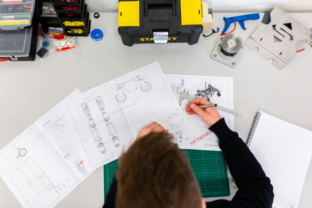
In many production plants, the problem is not the part failure itself, but the lack of possibility to quickly reproduce it. This applies especially to older machines for which technical documentation is incomplete, unavailable or simply no longer exists. In such situations, replacing the entire machine is often not financially justified, while the availability of original spare parts may be limited. This is where reverse engineering combined with CNC machining becomes useful. This process makes it possible to reproduce a part based on a physical sample, prepare new technical documentation and manufacture a component adapted for further operation within the existing system. When Reverse Engineering and CNC Machining Are an Alternative to Buying New Parts Not every part needs to be recreated from scratch, but in many cases this is the most reasonable solution. This is especially true when machine downtime generates real costs and obtaining the original part turns out to be difficult or unprofitable. This applies in particular to older machines, for which the availability of spare parts is limited or the delivery time does not meet the needs of continuous production. Lack of Technical Documentation and the Need to Reproduce a Component In the case of older machines, technical documentation is often unavailable. This applies both to equipment that has been withdrawn from production and to parts that were designed many years ago without a digital documentation archive. In such situations, the worn part becomes the only reference point. If its condition and preserved geometric features allow for reliable analysis, it is possible to prepare new technical documentation and manufacture a replacement part using CNC machining. Worn or Unavailable Parts in Older Machines The problem concerns not only documentation, but also part availability. In maintenance practice, a frequent challenge is dealing with components that are no longer offered by the manufacturer or whose delivery time is unacceptable from a production perspective. In such cases, reverse engineering can significantly shorten the path from identifying the problem to manufacturing a new part, without the need for costly modernization of the entire machine. What the Reverse Engineering Process Looks Like Before CNC Machining Reproducing a part based on a worn component is not simply about copying its shape. Understanding the function of the subassembly, its geometry and the conditions in which it will continue to operate is essential. The aim of the process is to prepare a solution that can operate again within the existing system, not merely to recreate the appearance of the element. Analysis of the Physical Part and Assessment of Reproduction Possibilities The first stage is the analysis of the available part. Its technical condition, degree of wear and whether its preserved geometric features allow reliable reproduction are assessed. Not every worn part can be directly replicated. In some cases, it is necessary to take operational wear into account and separate the original geometry from changes that occurred during use. Recreating Geometry and Preparing Technical Documentation After the analysis, it is possible to prepare new technical documentation, which becomes the basis for further production. At this stage, the physical part is no longer just a sample, but becomes a source of information needed to reproduce the component. The documentation must include not only dimensions, but also key functional features that will be important during the operation of the component. Selection of Material and Production Assumptions Recreating the geometry does not always mean automatically recreating the entire solution one-to-one. The material, the way the component operates and its service requirements are also important. In some cases, it is necessary to take into account production parameters different from those used in the original solution, especially if the reproduced component is to operate under changed conditions. The Role of the Technologist in Reverse Engineering and CNC Machining Effective reverse engineering requires a combination of measurement, technological and production knowledge. The available part itself does not always provide a complete picture of the parameters needed to reproduce it, which is why proper interpretation of the collected data and assessment of production possibilities are crucial. From a technological perspective, it is important to translate the information obtained from part analysis into documentation that enables the new component to be manufactured using CNC machining. It is equally important to consider the function of the element, how it works with other parts and the operating conditions in which it will continue to be used. This is the area handled by the technologist preparing the production process. We describe what this role looks like in practice in more detail in the article: “From documentation to stable production – the work of a technologist at SIM Gdynia” Which Components Are Most Often Reproduced Through Reverse Engineering and CNC Machining? Reverse engineering is used wherever quick reproduction of a part helps reduce downtime or avoid costly replacement of a larger system. Most often, this concerns parts of production machines, wear components and mechanical parts that deteriorate over time, while replacement with original equivalents is difficult. Most commonly, these include: This is especially important in plants that modernize existing machine parks and want to extend the life of proven equipment without having to fully replace the infrastructure. Summary Reverse engineering makes it possible to reproduce worn or unavailable components based on physical samples and prepare new technical documentation for further production. Combined with CNC machining, it enables the production of spare parts for existing machines without the need to replace entire devices. In many cases, this solution helps reduce downtime and maintain the continuity of machine park operation. At SIM Gdynia, we provide CNC machining of parts for demanding industrial applications, including cases where the starting point is an existing component that needs to be
Tightness and Surface Smoothness in CNC Machining of Hydraulic Power Components
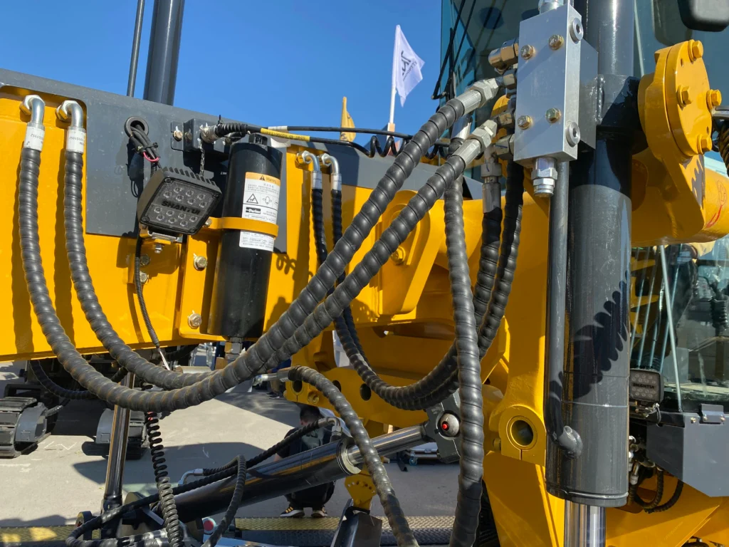
Hydraulic power is an area where even minor quality deviations can affect the operation of the entire system. Component tightness, stability of operating parameters and durability of cooperating elements depend not only on the design, but also on the quality of each manufactured part. That is why CNC machining of hydraulic power components requires high precision, control of process parameters and repeatable quality. Dimensional accuracy, surface quality and the compatibility of cooperating elements are particularly important here, as they are responsible for maintaining pressure and ensuring proper seal operation in the finished system. Why CNC Machining of Hydraulic Power Components Requires High Precision In hydraulic systems, tightness is not only a feature of a single component. It is the result of many elements working together, all of which must maintain the right dimensional and surface parameters. Even small deviations can affect the operation of the entire system. In hydraulic power systems, maintaining the correct working pressure is crucial for performance and operational safety. Leaks may lead to pressure drops, reduced efficiency and faster component wear. For this reason, CNC machining of hydraulic components requires a high level of manufacturing accuracy. This applies both to sealing surfaces and to cooperating elements that must maintain geometric compatibility within the entire system. We discuss manufacturing accuracy and tolerance classes in more detail in the article: “Dimensional and fit tolerances – how to optimise IT classes in CNC machining to avoid overpaying?” Surface Smoothness in CNC Machining and Seal Effectiveness One of the key quality parameters in hydraulic components is the condition of the surface after CNC machining. The effectiveness of cooperation with seals and the long-term durability of the system largely depend on this parameter. Surface quality affects not only tightness, but also the stability of cooperating elements and the rate of wear during operation. How Surface Roughness After CNC Machining Affects Seal Performance Excessive surface roughness may lead to faster seal wear. Irregularities increase friction and place greater stress on sealing elements during operation. In the long term, this may result in loss of tightness, reduced system efficiency and the need for earlier replacement of wear components. Surface quality requirements depend on the function of a specific component and its operating conditions. Different parameters will be important for static components, while others will matter for elements operating in continuous motion. Is an Extremely Smooth Surface After CNC Machining Always Beneficial? High surface quality is important, but oversimplifying this issue can lead to incorrect assumptions. An extremely smooth surface does not always mean better operating conditions. In some applications, a specific surface structure helps maintain proper lubrication conditions and stable cooperation with seals. Required surface parameters are selected depending on the component’s function and operating conditions. Tolerances and Quality Control in CNC Machining of Hydraulic Components The tightness of a hydraulic system results from the compatibility of many parameters. Surface quality alone is not enough if the elements do not maintain the required dimensional accuracy. In components operating under pressure, even minor deviations can affect the fit of cooperating parts and the stability of the entire system. Fits and Manufacturing Accuracy in CNC Machining In hydraulic components, fits and dimensional compatibility of cooperating elements are highly important. Dimensional deviations may affect the tightness of connections or the operation of moving mechanisms. Problems of this type often appear only at the assembly or operating stage, when individual elements begin to work together under load. Measurement and Surface Control After CNC Machining Quality control in the production of hydraulic components includes both dimensional measurements and the assessment of surface parameters. Verification of the part geometry makes it possible to confirm compliance with technical documentation, while surface quality control directly affects the functionality of the finished component. We discuss methods of measuring and inspecting parts in more detail in the article: “How to measure workpieces in CNC machining? Measurement methods and their applications” For elements responsible for tightness, what matters is not only a single measurement result, but also repeatable quality across successive parts. Repeatability of the CNC Machining Process and Component Tightness The production of hydraulic components requires a stable process. Even a correctly manufactured part does not guarantee the quality of the entire series if process parameters are not kept under control. Repeatability is particularly important wherever components operate under pressure and must maintain identical functional properties regardless of the production batch size. Which Hydraulic Power Components Require the Highest CNC Machining Precision? Not all hydraulic system components are equally demanding. The highest precision is required where even small manufacturing differences may affect tightness, fluid flow or the stable operation of the entire system. The most demanding components include: In their case, not only dimensional accuracy matters, but also surface quality and manufacturing repeatability. Valve bodies are particularly demanding, as their manufacturing quality directly affects fluid flow and the functionality of the entire system. Both the geometry of the part and the surface quality of flow channels and cooperating surfaces are important here. A similar situation applies to sleeves and pistons operating in motion, where even small deviations can increase friction, accelerate seal wear or affect component stability. Summary Hydraulic power is an area where CNC machining requires particularly strict quality control. System tightness depends on many factors – from dimensional accuracy and surface quality to the stability of the entire production process. In the case of components operating under pressure, even minor manufacturing differences can affect the durability and reliability of the finished solution. That is why repeatability of parameters and high manufacturing quality are crucial in the production of such elements. At SIM Gdynia, we provide CNC machining of components for demanding industrial applications, where tightness, accuracy and manufacturing repeatability are of key importance.
Mechanical Assembly of Subassemblies – Why It’s Worth Outsourcing Complete Modules to a CNC Machining Supplier
Mechanical assembly in modern industry is increasingly becoming integrated with the manufacturing process instead of functioning as a separate stage. More and more companies are asking whether it is better to coordinate multiple suppliers or outsource the production of a complete module to a single partner. From our experience, combining CNC machining and assembly helps reduce fitting issues between components and simplifies production management. Is It Worth Combining CNC Machining and Assembly in One Place? In the traditional production model, individual components are manufactured by different suppliers. Only after delivery are they assembled and completed at the customer’s facility. This model requires coordination of multiple orders, shipments, and quality control stages. Each of these elements increases the risk of errors and makes it harder to maintain control over the entire process. As a result, the likelihood of delays and inconsistencies between suppliers grows. Reducing Organizational Costs Outsourcing the production of a complete module simplifies production management. Instead of handling multiple ERP entries and coordinating several purchase orders, you work with one consistent production order. It also reduces the number of administrative operations related to order processing and delivery control. This is especially important in projects involving a large number of components that require coordination between multiple suppliers. Shorter Lead Times in CNC Machining and Assembly Processes In an integrated model, the process runs more smoothly because components move directly from one production stage to the next without the need to organize transportation between suppliers. This eliminates downtime and reduces waiting times for subsequent operations, resulting in faster project completion. Reducing lead times is important not only operationally but also from a business perspective. It allows products to be introduced to the market faster and helps minimize costs associated with production downtime or project delays. Fits and Tolerances in CNC Machining – One Supplier, One Responsibility Most assembly problems occur where components produced by different suppliers must fit together. Even small differences in tolerances can prevent proper assembly of a subassembly. In such cases, the issue is not caused by a single mistake, but by the accumulation of minor deviations that only become visible during final assembly. We discuss the topic of tolerances and component fitting in more detail in the article: “Dimensional Tolerances and Fits – How to Optimize IT Classes in CNC Machining to avoid Overpaying?” Eliminating Assembly Issues When an entire module is handled by a single supplier, tolerances are adjusted already at the production stage, and any deviations can be corrected immediately. Components are verified as a complete system, which helps avoid assembly problems later on. This is especially important in serial production, where assembly repeatability directly affects production time and costs. Quality Control of the Entire Subassembly Quality control for a finished subassembly includes not only checking individual dimensions but also verifying overall functionality. Fits, movement resistance, and — if required by the project — sealing performance are tested. Thanks to this, the completed module can be used directly in further production stages. We describe quality control and measurement methods in more detail in the article: “How to measure workpieces in CNC machining? Measurement methods and their applications.” How Production and Assembly Integration Impacts the Project Combining CNC machining and assembly allows for a broader perspective on the entire production process. In practice, this means the possibility of simplifying the design or selecting technologies more effectively. Integration of CNC Machining and Assembly Processes In the integrated model, one supplier is responsible for the entire process — from CNC machining and finishing operations to part preparation and final assembly. This approach makes production planning easier and reduces unnecessary operations. As a result, subsequent production stages are better aligned, and the number of intermediate operations is minimized. This has a direct impact on overall process efficiency. Management of Standard Components As part of the module production process, procurement of standard components is also handled, including: This allows the entire subassembly to be produced as one cohesive order. It reduces the risk of using incorrect components and simplifies quality control of the complete assembly. Where Errors Occur in CNC Machining and Assembly Projects In demanding industries such as energy or heavy machinery, failure of a single component can lead to serious consequences. In more complex assemblies, even small errors may result in operational issues or the need for modifications during assembly. Most often, these problems arise from discrepancies between documentation and the actual execution of parts by different suppliers. The Importance of Process Control In the integrated model, assembly takes place in controlled conditions, reducing the risk of contamination and enabling material verification at different stages of the process. As a result, finished subassemblies are more repeatable and less prone to operational errors. Why the Price of a Single Part Is Not the Total Project Cost The cost of an individual component is only part of the overall project cost. Storage costs, assembly organization, team working time, and the risk of errors and rework are equally important. Only by considering all these factors can the actual total production cost be properly evaluated. For this reason, cost analysis should include the entire project lifecycle, not just the price of a single component. Summary Outsourcing mechanical assembly together with CNC machining helps simplify production organization, shorten lead times, and reduce the risk of errors at component interfaces. This results in greater process predictability and improved quality control of the finished subassembly. For more complex assemblies, consistency throughout the entire process — from CNC machining to final assembly — is essential. At SIM Gdynia, we provide production and assembly of components, ensuring proper fit, repeatability, and compliance with project requirements.